Tutorial SVG Mapping with the MXWendler Automatic Calibration: Difference between revisions
| Line 54: | Line 54: | ||
:right click = menu | :right click = menu | ||
The 3D Mode will be used to match picture and 3D object. <br> | |||
8. Load the picture (not the .svg) in the layer manager. '''(C)'''<br> | |||
9. Right click on the keystone interface and select: | |||
:Preview source texture - “Render Output”. | :Preview source texture - “Render Output”. | ||
: Open the UV Map Projector´s dialog (yellow rectangle). '''(D)''' | Now we can work with the “Transformation Dialogs”. In the 3D Mode we have three items: <br> | ||
the .svg object, the Camera/Projector and the UV Map Projector, and each one has it´s own transformation dialog. They allow an accurate manipulation of the item´s characteristics. <br> | |||
To open one of them, right click on the relative object and select: “Show Transformation Dialog”. <br> | |||
10. Open the UV Map Projector´s dialog (yellow rectangle). '''(D)''' | |||
:Set the values to make the image fit your object. | :Set the values to make the image fit your object. | ||
Revision as of 15:59, 25 March 2019
Stage Designer version 5.2
The new MXWendler mapping capabilities allow the user to precisely map an item in a matter of minutes.
In this tutorial we will map an object by taking a picture of it, manually tracking a vector of the contour and using the resulting SVG file to calibrate our mapping onto the object.
{{#mpdftags: pagebreak}}
This tutorial requires
- A video projector.
- A camera (a smart phone camera will do perfectly).
- A software capable of vector graphics and .svg export.
- (Inkscape is a freeware software that can be downloaded at:https://inkscape.org)
{{#mpdftags: pagebreak}}
Preparing the SVG vector file
1. Choose an object with a regular shape (will be easier to map) and put it in front of the projector.
2. Play an MXW Raster_White on the output to have an idea of the size of your projection.
3. Take a picture as close as possible to the beamer´s lens position, crop the picture and send it to the computer you are going to use.
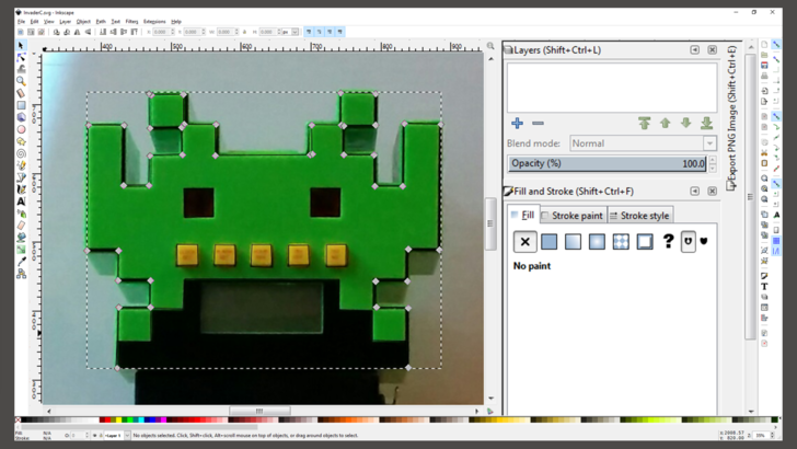
4. Open the picture with a vector graphics software, track the outline and save it as SVG file.
Mapping the projection trough the .svg model
5. Open MXWendler StageDesigner.
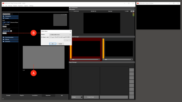
6. Go to the keystone tab and delete the keystone element. (A)
7. In keystone/keystone select: “Keystone 3D” and “Create Element”. (B)
- Select your projector as output and the .svg as model in the dialog.
Setting the mapping with the 3D Mode
As projector and model are confirmed the keystone interface will open in 3D Mode, to use this interface the following commands are needed:
- click + drag = rotate
- mouse wheel = zoom
- ctrl + click + drag = move
- right click = menu
The 3D Mode will be used to match picture and 3D object.
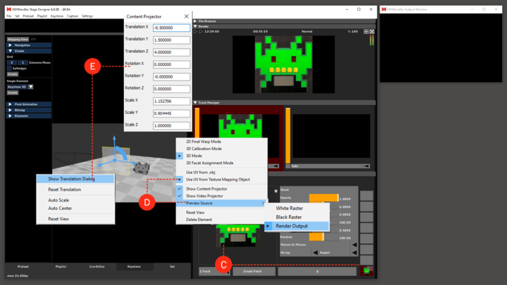
8. Load the picture (not the .svg) in the layer manager. (C)
9. Right click on the keystone interface and select:
- Preview source texture - “Render Output”.
Now we can work with the “Transformation Dialogs”. In the 3D Mode we have three items:
the .svg object, the Camera/Projector and the UV Map Projector, and each one has it´s own transformation dialog. They allow an accurate manipulation of the item´s characteristics.
To open one of them, right click on the relative object and select: “Show Transformation Dialog”.
10. Open the UV Map Projector´s dialog (yellow rectangle). (D)
- Set the values to make the image fit your object.
3D Calibration Mode
Now we are ready to map our item. Through the calibration, the software will let you do a mapping just by setting up 4 points (Vertices).
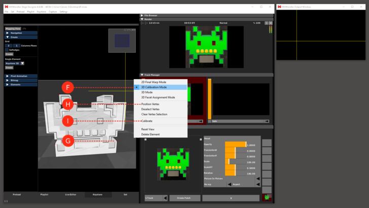
7. Right click on the background and select “3D Calibration Mode”.
- Choose and select four corners of your object.
- Right click on one of the red dots.
- Select “Position Vertex”.
- Two yellow crossing lines will appear in your output.
- Select the corresponding point on the physical object.
- Repeat for each of the four red dots .
- Right click on “Calibrate”.
2D Final Warp Mode
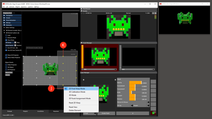
At this point our projection should be on the object but we may want to refine our work. For this purpose we will use our keystone interface.
8. Right click on the background and select “2D Final Warp Mode”.
- (E) Go to the element sub menu.
- Set the values and move the pivots to match your output to the object.
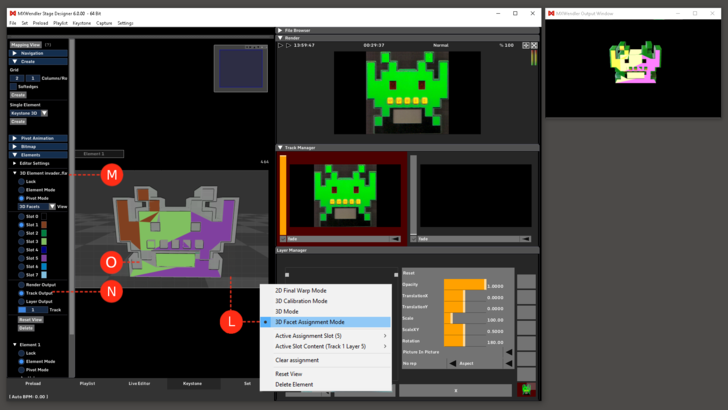
3D Facet Assignment Mode
9. Right click on the background and select “3D Facet Assignment Mode”.
- This section allows the user to assign layers and tracks to specific areas of the model.
- Right click and select current assignment slot: slot 1.
- Right click and select the current slot content: track2 layer1.
- Select the content for two slots more.
- Start to map the output on the polygons of the .svg/3D model.
- Switch to 3D Mode to see the result.
