User Interface
User Interface - Output
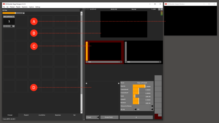
Output Window: the signal to be sent to output devices is distributed via the Output Window. The Output Window can be set to any size or position, and the caption bar can also be hidden. This window is in principle positioned where the video signal outputs to the projectors. (A)
Output Preview: the output preview enables control over the output video image. "Final Transforms" or "Final Effects" can also be incorporated here. (B)
Tracks: there are different output tracks. The red-colored track is active for editing; corresponding layers are visible for processing. (C)
Layermanager: the Layermanager enables the layer-based processing of video media, a procedure well known in image processing. Individual image components are composed together in a stack, from bottom to top. (D)
User Interface - Resettable Runtime Counter
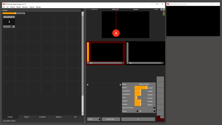
Runtime Counter: the Runtime Counter shows the time since the start of the session. The Counter can be set back to zero with a simple double-click on the counter itself or by creating an IO event and selecting '/mxw/render/runtime' as receiver (the event can be activated, for instance, at the start of the playlist). (A)
User Interface - Internal File Browser
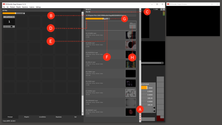
Access the Internal File Browser: open the Internal File Browser by clicking and dragging the dots to the right. Here you can drag & drop your media to the preload. (A)
Address Bar: the address of the current folder. You can double click on the bar and type the address you need to go to and click Ok. (B)
This PC: goes to the root folder of the hard disk, where you see the drives that your system has. (C)
Zoom: zoom in or out in the folder to see thumbnails or just file names and details. You can change it either by mouse wheel or by clicking and dragging it. (D)
Reset Zoom: resets the zoom to it's default amount. (E)
Reload Directory: reloads the directory so that the changes to the files are updated. (F)
Auto-Close Filebrowser: when selected, the filebrowser will be automatically closed when you click somewhere else. (G)
One Up: moves to the parent folder of your current position. (H)
User Interface - Preload
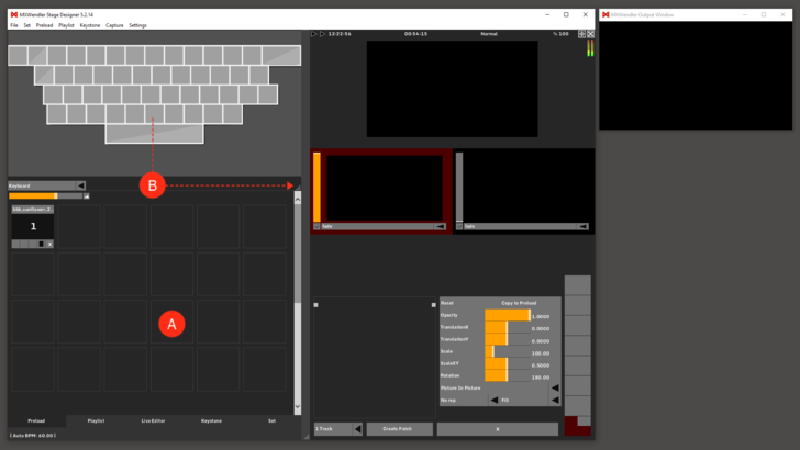
Preload: media are stored here for later playback. One media file can be stored per tile. The software can store media files in its memory. Parameters can be assigned to media (e.g. effects, position and transparency). These media are played back as specified through the Preload Index - by the playlist, or directly using IO commands. (A)
Action Pad: the Action Pad is used to playback media directly, and to program events via drag&drop with the keyboard, Midi, and DMX. The keyboard graph shown appears by pulling down the action pads bottom corner on the right (see arrow). (B)
User Interface - Playlist
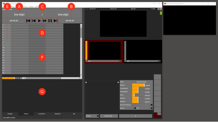
Cue Names: shows the title of the next cue. (A)
Timers: there are two timers: the one on the left shows the playback duration of the item in play in the first column (left). The one on the right shows the duration of the next cue. (B)
- use the first column of the playlist for autosteps or clips in automatic play mode to have the count of the time left in the actual cue.
Current Cue Position: shows the index number of the current cue, which will be played next. By double-clicking on it, you can enter the number or name of the cue you wish to go to. (C)
Playlist Buttons: from left to right: (D)
- Skip back to the beginning
- Skip one step back
- Play
- Seek forward
- Pause
- Skip one step forward
Comment Column: by double-clicking, a user-defined comment can be entered. (E)
Playlist: the cue commands are inserted in the cells. (F)
Cue Settings: the detail settings for the cues. (G)
User Interface - Live Editor
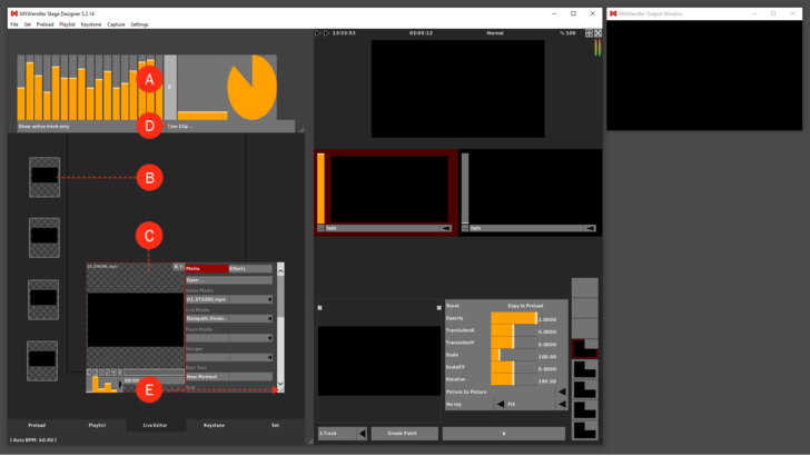
Spectrum Analyzer: audio and beat slider for the animation of visuals. See 'Tutorial Coupling Video with Effects and Audio Signals'. (A)
Storage Area: minimize a clip by dragging it to the exterior area. (B)
Work Area: maximize a clip for processing by dragging it to the center area. (C)
New Clip: a new clip will be created. The new clip has the standard footage as selected in the 'Windows' settings under 'Standard Clip/Timer'. (D)
Clip: an open clip in the work area. Open the clip settings by dragging the lower right corner (see arrow). Create a layer (send the clip to the Layermanger) by dragging the clip to the Layermanager, or by clicking on the 'Plus' sign. (E)
User Interface - Live Editor - Expressions
Expression: hold Shift and drag any moving fader (e.g. Spectrum Analyzer or Clip Progress) to any visible parameter (e.g. Layer or Effect parameters) to connect the two values through an Expression. (A)
The movement of the first bar is going to influence the value of the second one.
The Expression can be minimized and recalled: to see the expression, double click on the red part of one of the selected bars. To minimize it, just hit the minimize button or double click on one of the bars again.
Expression Editor: open the Editor with a double click on the Expression. (B)
The user can modify the mathematical properties of the relation between the two connected values.
Base and Range can be used to calibrate the responsivity of the Scale to the low frequencies of a sound.
Example of sound to light calibration:
- 1. Play a video and connect with shift+drag&drop, a moving channel of the Spektrum Analyzer to Scale.
- 2. Open the Expression Editor, bring 'Range' to '0' and move 'Base' until you get close to the target default value (Scale:100).
- 3. Now, moving the 'Range' up should increase the influence of the sound on the video 'Scale'.
Tips: an expression can be stored and recalled in a Patch, it can be paused. It can be used in chain and also to connect different parts of the software! (e.g. Spectrum Analyzer - Scale - Keystone - IO Animator)
User Interface - Keystone: Keystone
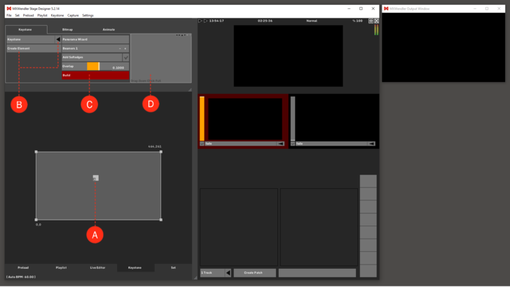
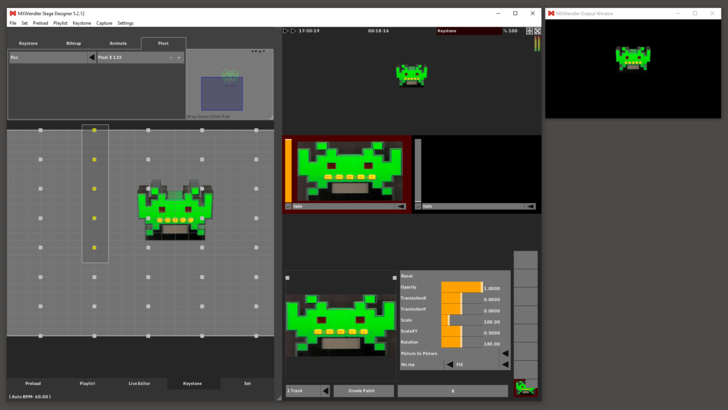
Keystone Element: activate/lock the Keystone element by double-clicking on its basis pivot. Delete the Keystone element by clicking on 'x'. (A)
Create Element: select the desired element type in the dropdown menu and click on 'Create Element'. (B)
Panorama Wizard: the number of projectors, the Softedges plus the overlapping can be edited in the 'Panorama Wizard'. Click the 'Build' button to activate the changes. (C)
Keystone Navigator: to zoom into a detail draw the desired sector in the overview display in the navigator. (D)
User Interface - Keystone: Bitmap
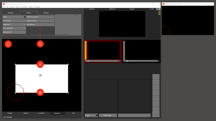
Bitmap Interface: draw a mask onto the bitmap interface. (A)
Bitmap Mask Pivots: adjust the bitmap mask to the projection by dragging the pivots. (B)
Drawing Tools: the following drawing tool parameters can be selected in the settings: (C)
- Tool type (brush/crosshair/crosshair with comment/polygon)
- Pen size
- Pen weight
- Pen sharpness.
Import/Export: you can export the bitmap mask you created with MXWendler as .png file and edit it with an image-processing program (e.g. Photoshop/Gimp). You can import and use masks you created with external programs as well. Just make sure that you use .png as the file format. Click on 'Clear Bitmask' to delete existing masks. (D)
User Interface - Keystone: Animate
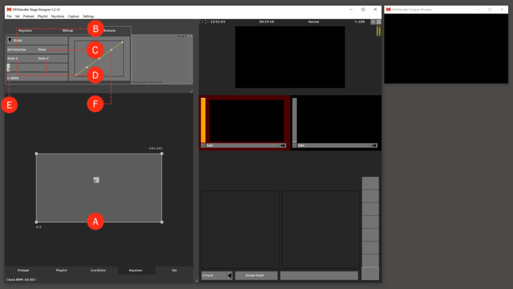
Animate Interface: with this interface, you can animate your output correction. See 'Tutorial Colored Output with Animations'. (A)
Set Selection: click this button to set the selection of the animated keystone pivots. (B)
Show: click this button to show the selection of the animated keystone pivots. (C)
State A / State B: (D)
- State A marks the starting position of the animation.
- State B marks the end position of the animation.
Time Slider: The animation can be triggered with the slider. (E)
Animation Curve: the animation cycle, shape and format can be modified using the animation curve. (F)
User Interface - Keystone: Element
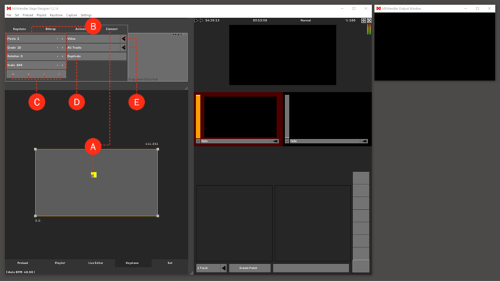
Keystone Element: for reaching the keystone-elements dialogue activate the element tab. The element tab appears when an element is selected. (A)
Element Settings: (B)
- Pivots: shows the numbers of pivots per side. More pivots allow finer positioning.
- Grade: shows the subdivision of the surface in the rendering. Higher degrees make smoother curves but use more resources.
- Rotation: rotating an element about the Z-axis. In one-hundredth of a degree. Element rotation 9000 = 90 degrees.
- Scale: scale the element up/down.
Element Layers: the arrangement of the elements can be adjusted by four buttons: (C)
- ++ = to the foreground | + = one level forward
- - = one level back | -- = to the background
Duplicate: duplicates an element. (D)
Table of Contents: (E)
- Content: content of the element. Video, Raster, Colour or Transparent.
- Content Source: rendering output of a particular layer, track or the complete output.
User Interface - Keystone: Pivot
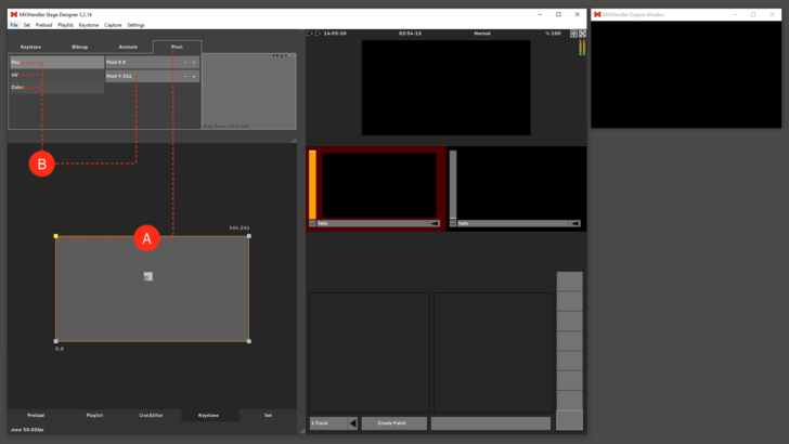
Keystone Pivot: for reaching the keystone pivot dialogue, activate the pivot tab. The pivot tab appears when a pivot is selected. (A)
Pivot Settings: the position (POS), the displayed section (UV) and the COLOR can be adjusted for every single pivot. (B)
User Interface - Keystone: DMX
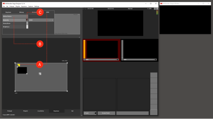
DMX Grabber: for reaching the keystone DMX dialogue activate the DMX tab. The DMX tab appears when a DMX element is selected. (A)
Define Fixtures: grabber characteristics, e.g. DMX file structure and resolution can be defined in the fixtures. See 'Tutorial Capture Output Sections with Artnet, DMX and Network Grabbers'. (B)
Color Correction/Color Damping: here the overall brightness, the dynamic and the chromaticity of the grabber can be adjusted separately. (C)
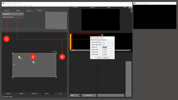
User Interface - Keystone: Network
Network Grabber: to reach the Keystone-Network dialogue activate the Network tab. The Network tab appears when a Network element is selected. (A)
Settings Dialog: position and resolution of the Network Grabber can be defined in the settings. (B)
Make SDP File: this file describes the stream and can be opened on another system in the network. (C)
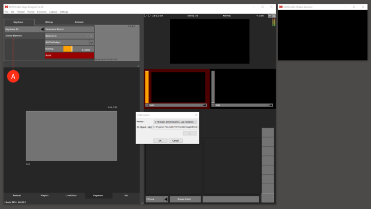
User Interface - Keystone: 3D
Create Element: after clicking on “Create Element” a setup box will appear: (A)
- Select your output and the desired .svg or .obj file as model in the dialog.
Check 'Tutorial SVG Mapping with the MXWendler Automatic Calibration' to have a clear idea of the 3D Keystone usage.
User Interface - Keystone: 3D Mode
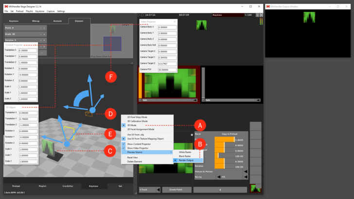
3D Mode: the 3D Mode is automatically selected by creating the 3D element. To reach the 3D Mode later, right-click on the keystone element and select 3D Mode. (A)
Preview source texture: it is possible to see either a raster image or a preview of the intended projection directly on the 3D object.
To activate it, right-click in the keystone element and then select ”Preview Source” – “Render Output”. (B)
The 3D mode is based on three items:
the 3D Object: is the 3D model of the object that we want to use for our projection. It has to be an .svg or .obj file. (C)
The Camera/Projector: represents the source of the projection. (D)
The UV Map Projector: is the 2D layer correspondence between the source intended projection and the 3D object. Either the object (.obj) provides the so-called UV mapping itself as a part of the .obj file or it must be specified by a UV map projector. (E)
The properties of each of these items can be defined through the:
Transformation Dialogues: the transformation dialogues are used to adjust the size and position of all the elements. Transformation objects can be opened with a double click on the object or on the projector parts. (F)
User Interface - Keystone: 3D Calibration Mode
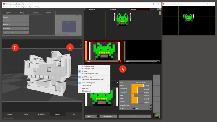
3D Calibration Mode: to reach the 3D Calibration Mode, right-click on the keystone element and select 3D Calibration Mode. This mode allows a really fast positioning of the projection on the physical object we are simulating. (A)
Vertex: any corner of the object can be selected as “vertex”. To calibrate the projection four “vertices” are needed. (B)
Positioning Lines: positioning lines will be shown in the output. They will be used to match the projection with the object. (C)
User Interface - Keystone: 2D Final Warp Mode
2D Final Warp Mode: for reaching the 2D Warp Mode, right-click on the keystone element and select it. This mode allows refining the projection on the physical object. (A)
Usage: this part of the interface is based on the normal keystone element usage. Check the entry for User Interface KEYSTONE – KEYSTONE for detailed guidelines. (B)
User Interface - Keystone: 3D Facet Assignment Mode
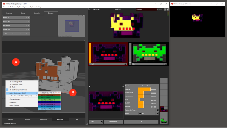
3D Facet Assignment Mode: for the 3D Facet Assignment Mode, right-click on the keystone element and select it. This mode allows to assign a specific Layer or Track output to an area of the object surface. (A)
Assignment Slots: up to eight slots can be applied at the same time on the polygons composing the 3D object´s surface. (B)
User Interface - Set
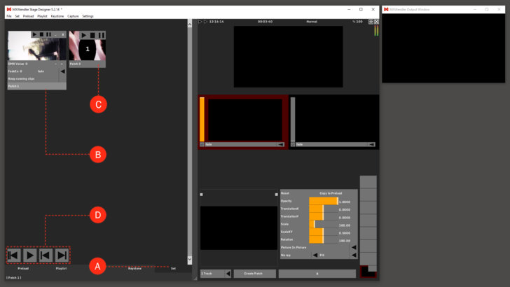
Set: in a set are so-called ‘patches’, complete compositions with multiple layers, as well as all parameter- and media information. With a single click, the full scene that is being played back can be saved into a patch. This can be later retrieved individually, or as a sequence. Please notice for latency-free output that patches are just ‘lightweight’, only the references but not the media itself will be loaded. (A)
Open Patch: IO Index: (B)
- The patch will be triggered when a value is sent via script, DMX or Midi.
Closed Patch: the patch can be played, stopped and paused. (C)
Set Buttons: with the buttons, the set can be played sequentially. From left to right: (D)
- Back to the beginning
- Play
- One step back
- One step forward.
User Interface - Capture
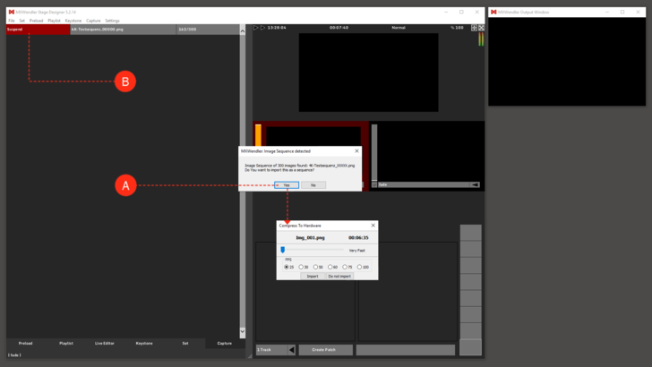
Compress to Hardware: this dialogue appears when an image sequence or a video clip gets converted into the internal codec. (A)
Suspend: the compression is paused. (B)
